- Herramientas de edición
 Introducción
- Edición gráfica
- Introducción
- El área del dibujo
- Iniciar y terminar una sesión de edición en gvSIG
- Procedimientos para la entrada de ordenes
- Configurar las propiedades de una sesión de edición
- Deshacer/rehacer acciones en una sesión de edición
- Acciones posibles en una sesión de edición
- Introducción
- Seleccionar
- Copiar
- Simetría
- Rotar
- Escalar
- Desplazamiento
- Editar vértice
- Polígono interno
- Insertar elementos de dibujo (puntos,líneas...)
- Edición alfanumérica (Tablas)
Herramientas de edición
Introducción
Edición gráfica
Introducción
gvSIG's CAD extension can make complex drawings from basic elements, such as lines, circles or polygons.
Features can be duplicated or modified as you wish by using actions such as copying or rotating.
To carry out these tasks, we need to know what type of layer is being edited. Once we know the type of layer, we can see which tasks can be carried out.
When the “Start edition” option is selected, the edition tool bar buttons appear. Only the buttons which can be used in the layer being edited are active. Thus, for example, if a points layer is being edited, the selection, move and point insertion tools are enabled

whilst if, for example, the layer is a line layer, all the tools are enabled except the point insertion tool.
Another tool which appears when an editing session is started is the command console or message and command area, located at the bottom of the graphic area. This tool allows you to input commands via the computer keyboard. These are then carried out in the graphic area.
El área del dibujo

If you select the “Layer” menu option then go to “Start edition”, the application window shows the following areas.
Menu bar: Menus with which you can access the application’s functions. The contents will change according to the situation, thus, for example, the "Geometry" menu will only appear when a layer is being edited.
Tool bar: Bar which shows the drawing command icons.
Graphic area: This takes up the majority of the display and is where the layer which is being edited is shown.
Command console: This is where the editor’s PROMPT is located (active line of the console). This means that the programme is ready to receive commands. When a command is input, the corresponding process is run and the messages, information or parameter requests are shown.
Status bar: This shows the scale, the measuring units, the absolute coordinates of the cursor position (X and Y) in these units and the projection.
Iniciar y terminar una sesión de edición en gvSIG
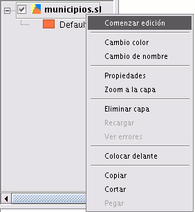
Firstly, enable the layer you wish to edit by selecting it in the ToC. Place the cursor over it and right click on the mouse. The contextual menu appears. Select the “Start edition” option.
N.B.: More than one layer can be edited and you can alternate what you do with them. However, whatever you do will only take effect on the active layer. To change the layer you are working on, select it in the ToC.
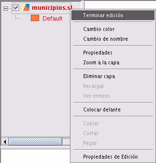
When you finish your editing session, go to the “Finish edition” option in the contextual menu.
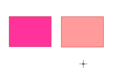
N.B.: The application will create a projection of the object you are working on to help you with the graphic editing. This will allow you to get a visual idea of the obtained result. The object projection will be shown in red.
The figure shows how a projection of the figure copied in a different colour is created during the copying process. This projection allows you to specify exactly where you want to place the new object in the graphic area.
Procedimientos para la entrada de ordenes
Introducción
There are three general mechanisms for the application to run user commands. The first mechanism is to select the command by clicking on the corresponding button in the tool bar. The second option is to activate the tool by selecting it in the menu bar (normally in the “Geometry” tab) and the third and last mechanism is by inputting commands in the command console using the keyboard.
Barra de herramientas
The edition tool bar appears when a layer is being edited. The tool bar icons will be activated according to the type of layer being edited.

Barra de menús
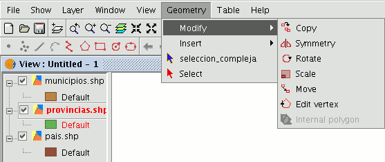
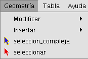
When an editing session starts, a new menu called “Geometry” appears in the bar from which we can access the different tools.
Consola de comandos
The commands, options, messages or parameter requests the programme runs are shown in the area called "Command console".
The bottom line of the command console is called the "line command" and shows the action the application is running. The command console area size can be increased or decreased. To modify its size, place the mouse pointer on the separation bar between the command console and the graphic area, left click on the mouse and move the bar up or down until it is situated in the required position.
When you have finished, let go of the mouse button. You can also hide the command console by clicking on the down-facing triangle situated at the top right of the console. To show the command console, click on the upward-facing triangle.
To input commands into the command console using the keyboard, write the name of the command or order and press “Enter”. Commands can be input in capital or small letters. When a command is input, a window or a set of options associated with this command appears.
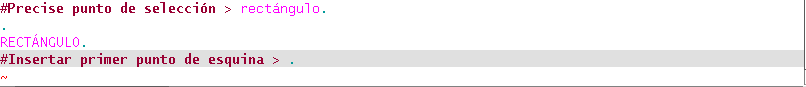
For example, if the “rectangle” command is input, a window will appear in which the definition of a corner point is requested. When the point has been inserted, a second point or “C” is requested to indicate that the object will be a square.
Configurar las propiedades de una sesión de edición
Introducción
When a layer editing session has been started, if you right click on its name in the ToC, a contextual menu appears in which, among other things, you can access the “Edition properties” to configure them.
Snapping
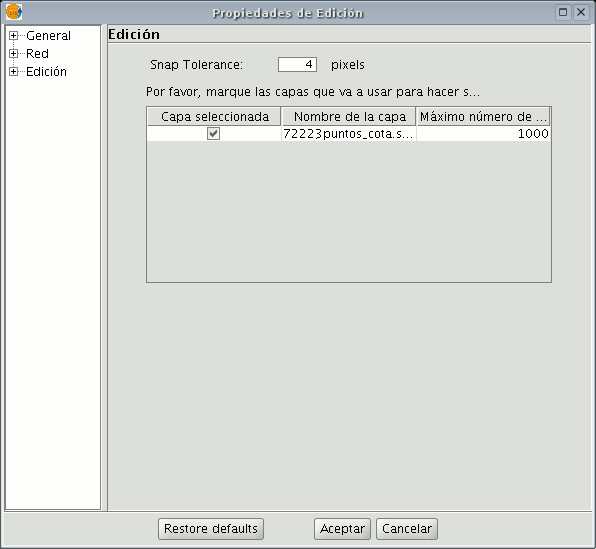
You can configure the “Snap tolerance” in the first editing page. “Snap” or “Snapping” is the process of moving an element until it coincides exactly with the coordinates of another element. If the “Snap tolerance” is 4 pixels, two elements which are the same distance or closer than 4 pixels will be joined in a common coordinate.
You can do element snapping between layers by enabling the corresponding check boxes in the “Selected” column.
You can modify the values of the "Maximum features edition cache" column to accelerate the snappings and handlers being edited. This is the maximum number of geometries you wish to work with in the cache.
Configurar la rejilla
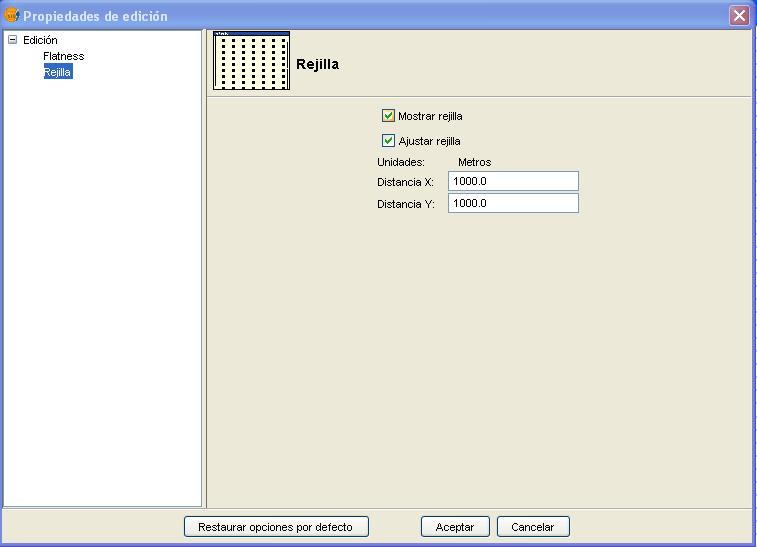
If you select “Grid” in the tree on the left, this will allow you to configure the grid’s properties.
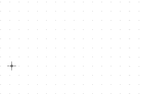
The grid is a point pattern which extends over the whole of the graphic area.
It is useful in that it allows you to line up objects and calculate the distance between them.
You can enable the “Show grid” and “Adjust to grid” check boxes and edit the distance between the grid points.
When the grid is shown, the graphic area will look like this.
Flatness
You can configure “Flatness” by selecting the corresponding option in the tree on the left.
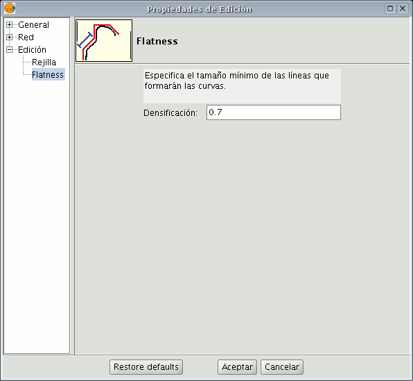
In gvSIG, a circle or any curved geometry is made up of straight sections. The flatness number you specify will define the maximum size of these sections.
Deshacer/rehacer acciones en una sesión de edición
Pila de comandos
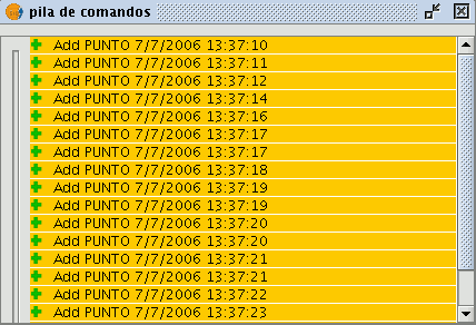
The command stack is a tool which allows you to undo/redo several commands at once. It also provides information about the commands carried out, such as the name and time they were carried out.
The command stack can be activated in different ways.
By clicking on the tool bar icon shown below.

By selecting the menu bar option "File" then going to "Command stack". The command stack saves all the commands given on the layer being edited since the last time it was saved.
You can select the commands you wish to undo in the slider control. You can move the slider control up or down until you have positioned it in the order in which you wish to continue working.
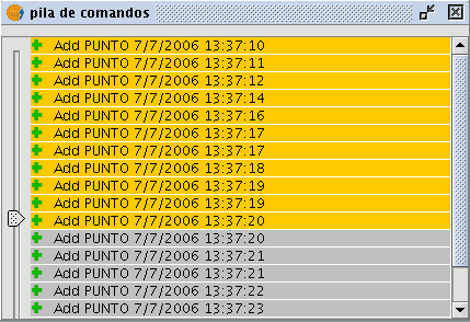
You must remember that you cannot undo one specific command, you have to undo all the commands given up to that point, i.e. we have to go to the last step we wish to keep and continue editing from this point. For example, let us suppose that we take eleven steps and when we reach the eleventh step, we realise that step number six is incorrect. We cannot simply go to step 6 and cancel it, we have to undo the eleventh, tenth, ninth steps, etc. until we get to the fifth one. The advantage of using the command stack is that we can undo all the changes at once without having to undo them one by one. In addition, we know which steps we are undoing.
Deshacer/Rehacer una acción
You can access Undo/Redo from the edition tool bar by clicking on the corresponding icon.

The button with the left facing arrow allows you to undo the last step. The button with the right facing arrow allows you to redo the last step you have undone.
Acciones posibles en una sesión de edición
Introducción
Editing commands are the set of orders used to edit or modify a drawing. More specifically, they cover all the processes and mechanisms required to modify and work with what has already been drawn.
gvSIG uses three different ways to run these commands.
- By clicking on the corresponding button from the tool bar.
- From the menu bar.
- By writing the command in the command console.
Seleccionar
Selección simple
To select one of the drawn objects in the layer we are editing, click on the "Select" button in the tool bar,

or go to the “Geometry” menu bar and then to “Select”.
Then click on the object you wish to select.
Selección compleja
You can access this button in the tool bar,

or by going to the “Geometry” menu bar then to “Complex selection”.
When the “Complex selection” tool has been selected, right click on the mouse in the graphic area. The following contextual menu will appear.
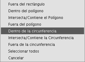
Click on the option you wish to use to select the elements.
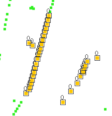
If you use the “Inside circle” option you can delimit a circle so that the elements you wish to select remain inside this area.
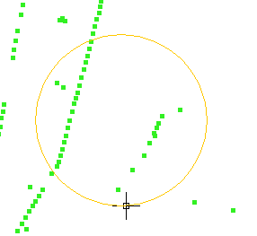
The selection result corresponds to the following image.
You can also write the “select” and “complex selection” commands in the command console. Command: “select” Write the command “select” in the command console.
When a message appears in the command console requesting you to add the selection point, input the coordinates of the object you wish to select.
If there is an object in the defined coordinates, it will be selected.

Command: “complex selection” Write the command “complex selection” in the command console and when the selection options appear, write the desired option.
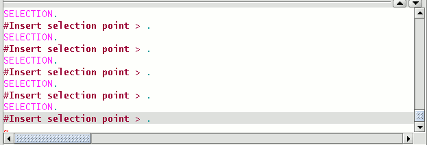
The options are shown with their names, and in square brackets ([]) the text you need to input in the command console to use the option.

If, for example, you wish to select the features that are in a polygon area, you need to write “complex selection” in the command console, press “Enter” and then select the “IP” option.
This allows us to indicate the coordinates of the vertices which will make up the polygon (when the coordinates of each of the vertices are indicated a polygon is drawn in the drawing window) and when it is finished, the elements which are inside it are selected so you can work on them.
The following image shows how a selection option is input.

The following figure shows the definition of the selection polygon in the graphic area.
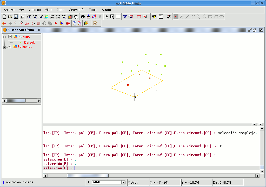
When the polygon is finished, the elements contained inside it will be selected so you can work on them.
- Selection options
- Outside rectangle [OR]: This allows you to delimit a rectangular area and select the elements which lie outside this area.
- Inside polygon [IP]: This allows you to draw a polygon area and select the elements located inside this area.
- Intersects with/Contains polygon [CP]: This allows you to draw a polygon area and select all the elements located inside it or which intersect with its perimeter.
- Outside polygon [OP]: This allows you to delimit a polygon area and select the elements which lie outside it.
- Inside circle [IC]: This allows you to delimit a circle and select all the elements located inside this area.
- Intersects with/Contains circle [CC]: This allows you to delimit a circle and select all the elements located inside it or which intersect with its perimeter.
- Outside circle [OC]: This allows you to delimit a circle and select the elements which lie outside it.
- Select all: This selects all the elements contained in the layer regardless of where they lie in it.
Copiar
This makes a copy of the objects you have selected. The elements copied will keep the same size and orientation as the originals. To access this tool, click on the “Copy” button in the tool bar

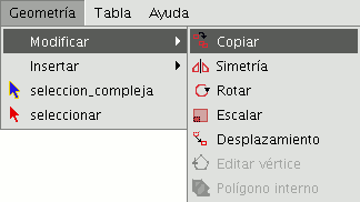
or go to the “Geometry” menu bar, then to "Modify" and "Copy".
The copying process is basically the same as the move process but the source objects do not move from their initial positions. New objects are created in the new location which are identical to the originals in size, shape and in the distance between them.
To make a copy, when the objects to be copied have been designated, two points need to indicated, the base point and the move point.
As with the rest of the tools, a projection of these objects will be shown in the view to specify the view location the copied objects are to be inserted in.
When the copied objects are situated in their location, click on the view again to set their position.
To copy objects from the command console, write the command "copy" when you have selected the objects you wish to copy, input the first move point and then the second point.
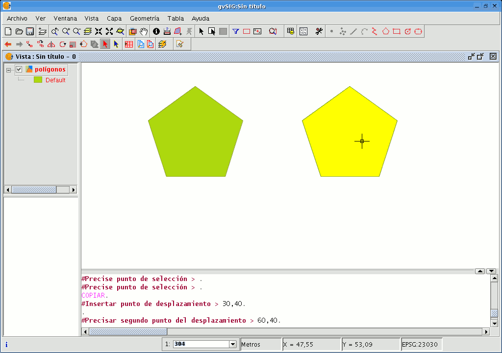
For example, when the command and the first move point have been input (30,40), the projection of the figure being copied appears. Input the second move point, (60, 40 in the example), and the new identical element will appear in the defined location.
Simetría
This tool allows you to make a drawing which is symmetrical to the selected one. You can access this tool by clicking on the “Symmetry” button in the tool bar

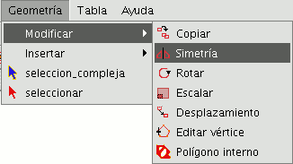
or by going to the “Geometry” menu bar, then to “Modify” and “Symmetry”.
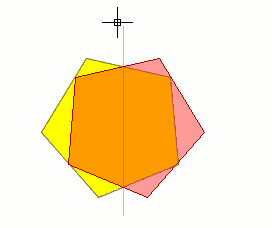
To obtain a symmetrical drawing in gvSIG, firstly select the element and then select the “Symmetry” option. Then, click on the display graphic area to insert the first symmetry axis point. gvSIG will then create a red projection of a figure which is symmetrical to the selected figure. You can then input the second point the symmetry axis will pass through by clicking on the graphic area again.
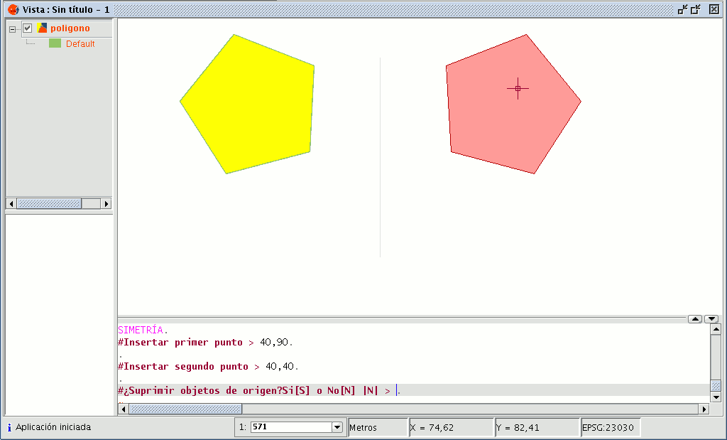
If you wish to run the tool from the command line, firstly write the command “symmetry”.
Input the first point the symmetry axis will pass through and press “Enter”. The console will then ask you to input a second point this axis has to pass through.
Input the point and press “Enter” again.
The console will ask you if you wish to keep the source object, write “Y” if you wish to keep it and “N” if you do not.
Rotar
You can use this tool to rotate the selected objects by taking a base point as the centre. You can activate this tool by clicking on the “Rotate” button in the edition tool bar

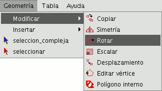
or by going to the "Geometry" menu bar, then to “Modify” and “Rotate”.
To rotate an element, first place the base point by clicking on the graphic area. Move the mouse, with the help of the projection that gvSIG uses to the effect, until the new position has been established.
Left click on the mouse in the view to define this point.
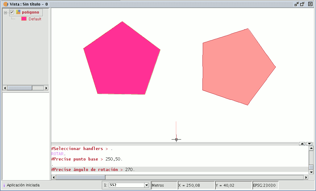
If you wish to rotate an element from the command console, select the object to be rotated, write the command “rotate” and input the first move point.
Then input how much you wish to rotate it in sexagesimal degrees.
The object will be rotated clockwise if you write a negative angle and anti-clockwise if you write a positive angle.
Escalar
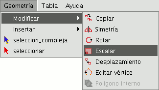
This command can be used to modify the size of the selected objects. Select this tool by clicking on the “Scale” button in the tool bar

or by going to the "Geometry" menu bar then to "Modify" and “Scale”.
There are two ways of scaling, either by indicating a scale factor or by reference. Scaling by “Scale factor” To graphically scale elements using a scale factor, select the objects whose size you wish to modify, activate the scale tool and set the base point. The application will create an image which will give you a reference point about the size of the objects you are modifying.
As you get closer to the point you have set as the base point, the elements you are working with will get smaller, whilst the farther away you move, the bigger they will get.
When the objects are the desired size, click on the drawing window again. The same scale factor is applied for both the X and Y coordinates.
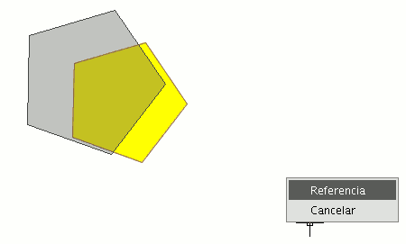
To graphically scale using the "Reference" option, select the objects and activate the “scale” command, then right click on the mouse inside the graphic area to show the tool’s contextual menu.
Select the “Reference” option. Indicate the points on the reference line and on the scale line as the messages in the command console are shown.
You can also use the “scale” command in the command console. When you have selected the objects to be scaled, write the command “scale” and then input the base point as shown in the following figure.
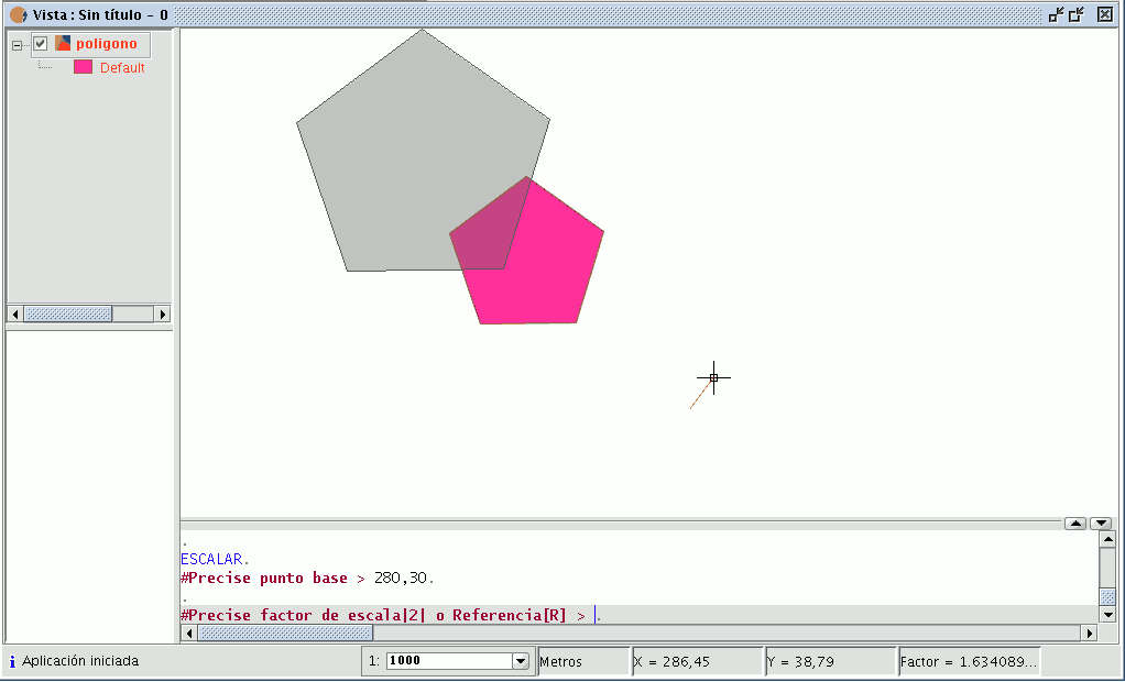
To increase the size of the objects you must input a scale factor which is greater than 1.
If you wish to reduce the size of the objects, the scale factor must be between 0 and 1.
If no value is input, gvSIG will use the scale factor 2 by default.
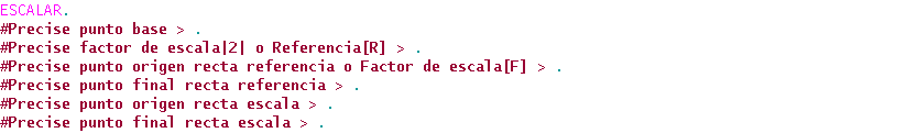
Scaling by “Reference” If you wish to scale using the "Reference" option, select the elements you wish to scale, choose the base point, then input the letter "r" into the command console to indicate that scaling by reference will be used.
Specify the source point and the final point of the reference straight line and then input the source point and final point of the scale line.
Desplazamiento
This tool allows you to move the selected objects from one point to another in the view by indicating a move vector. You can use this tool by selecting it from the tool bar by clicking on the "Move" button

or by going to the “Geometry” menu bar, then to “Modify” and "Move".
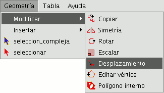
If you wish to move an element, select the object you wish to move and then activate the “Move” option. Click on the graphic area to define the move point.
gvSIG will create a red projection of the elements it is moving which can be used as a guide to position them in their new location.
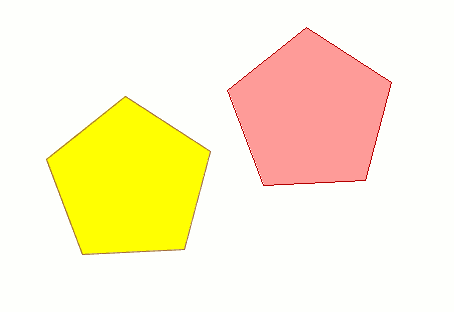
When the element is located in the desired position, left click on the mouse again to define the new position.
To use the “move” command from the command console, write the command “move”. The console will show a message requesting a move point. Input the point.
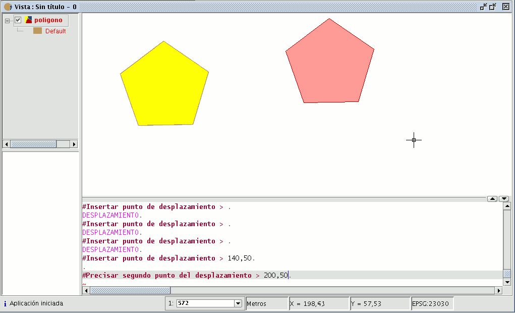
Then input the second move point. Press “Enter” and the object will move to its new position.
Editar vértice
This tool allows you to go through the vertices of the selected objects easily and carry out other actions, such as adding a new vertex or deleting the vertex which is being edited.
To access this tool, click on the “Edit vertex” button in the tool bar.

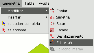
You can also access the tool by going to the “Geometry” menu bar then to “Modify” and “Edit vertex”.
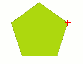
To edit the vertices of a figure, select the figure and click on the “Edit vertex” button in the tool bar.
A red pointer appears in one of the vertices of the figure you are editing.
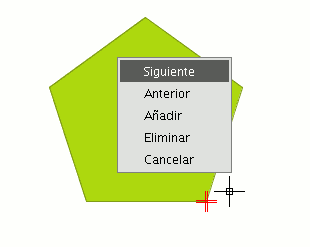
If you right click on the mouse, a menu will appear from which you can select the actions you wish to carry out.
If you click on the “Next” option, the cursor will move to the next vertex of the selected object.
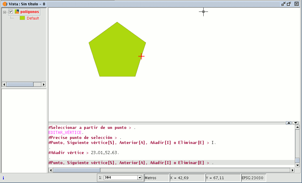
You can also access this tool from the command console. To do so, write the command: EDIT VERTEX.
If, for example, you wish to go through the vertices of an element, write the command and input the parameter “S” (next).
To go to the previous vertex, write the parameter “A”.
To delete a vertex write the parameter “E” and press “Enter”.
To add (insert) a vertex, write the parameter “I” and press “Enter”.
The X and Y coordinates of the new vertex will then be requested (remember that these coordinates should belong to the polygon perimeter).
Input the data in the console and press “Enter”.
A new vertex will be created in the figure.
Polígono interno
This tool allows you to create a polygonal feature inside an existing feature.
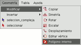
You can access this tool by going to the "Geometry" menu then to "Modify" and "Internal polygon”
or from the following tool bar button:

You can create an internal polygon, either graphically or from the gvSIG command console.
If you wish to create the polygon graphically, the polygon element layer must be in editing mode and you must select the polygon on which you wish to use the selected tool.
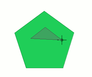
Activate the "Internal polygon" tool and place the cursor where you wish to insert the first vertex.
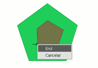
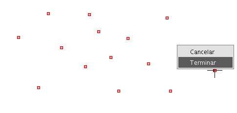
Then insert the vertices of the polygonal feature you wish to create. When you do not wish to insert any more vertices, right click on the mouse and select “End” from the contextual menu that appears.
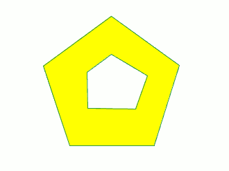
The corresponding internal polygon is created.
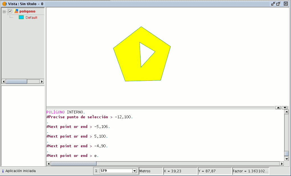
You can also use this tool from the command console. To do so, write the command “internal polygon” in the command line.
Then input the X and Y coordinates of the points which will correspond to the vertices of the new polygonal feature. When you have finished, write “e” to close the new internal polygon you have created.
Insertar elementos de dibujo (puntos,líneas...)
Introducción
This section deals with gvSIG’s drawing commands. The rest of the commands can modify the elements but with the exception of the “copy” command, they cannot create new features and we thus require the actual drawing commands to do so.
gvSIG includes basic drawing elements, such as lines, circles or polygons, which can be used to obtain any complex drawings.
All the elements you wish to insert need one or several points to be specified so that they are correctly placed in the drawing.
Remember that the tools to insert new elements vary according to the type of layer being edited. Thus, for example, a point can only be inserted in a point-type layer and is not supported by any other type of layer.
Punto
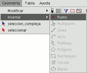
You can activate this tool by clicking on the “Point” button in the tool bar.

You can also activate it by going to the “Geometry” menu bar then to “Insert” and “Point”.
Insertar un punto por coordenadas
A point can be referenced in two ways:
- Console mode. The point coordinates are input numerically.
- Graphic mode. The point is indicated by using any of the pointer devices (normally a mouse).
The coordinates can also be:
- Absolute: They define a point based on the coordinate source (0,0).
- Relative: They define a point based on the last defined point.
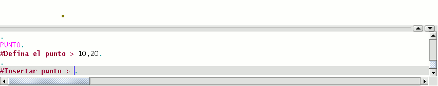
Inputting Cartesian coordinates.
Input the X and Y values separated by a comma (X,Y). The X value is the positive or negative distance, in units along the horizontal axis, the Y value is the distance in units along the vertical axis.
The values used to designate the points can be whole, decimal, positive or negative.
The absolute coordinate values are based on the source (0,0), which is the place the X and Y axes intersect. For example, the point 25,7 designates a point located 25 units away from the source on the X axis and 7 units away on the Y axis.
The relative values of the coordinates are based on the last input point. Use the relative coordinates when you know the coordinates of a point based on the previous point.
To designate a relative point, place the (@) symbol in front of the coordinates.
For example, the @1,2 coordinates determines a point 1 unit away on the X axis and 2 units away on the Y axis from the previously designated point.
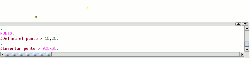
Inserting polar coordinates
To input polar coordinates, indicate a distance and an angle separated by the < symbol. For example, to designate a point 5 units away from the previous one with a 45 degree angle, write @5<45. The angles increase anti-clockwise and decrease clockwise. To move anti-clockwise, indicate a negative angle. For example, the 1<315 position is the same as the 1<-45 position.
Multipunto
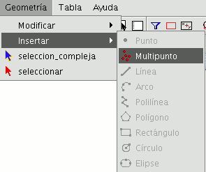
You can activate this tool by clicking on the “Multipoint” button in the tool bar

or by going to the “Geometry” menu bar then to “Insert” and “Multipoint”.
You can use the multipoint tool to create a drawing made up of a series of points which function as a single feature (i.e. we only need to select one of the points for the rest to also be selected). You need to bear in mind that this is not thus a points layer but a multipoint layer.
To insert a multipoint in the graphic area, select the tool and place the cursor over the part of the graphic area you wish to place the point. Left click on the mouse to insert the point. Repeat this step as many times as you wish. When you have finished adding points, right click on the mouse. A contextual menu will appear. Click on “End” to finish the new multipoint feature.
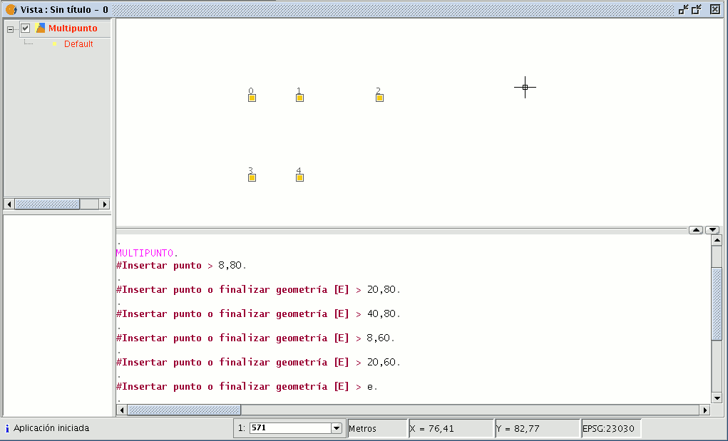
You can create a multipoint feature from the command console. To do so, write the command “multipoint”. Input the coordinates of each point you wish to add in the console and press “Enter”. To finish the insertion of the new multipoint feature, write the command “E”.
Línea
This command allows you to draw a line feature, which is actually a straight line segment. This feature is limited by its initial and final points. The final point may be the start of the next segment. When the first point has been inserted an elastic line appears on the display. You can use the mouse to determine where you wish the final point to go. As with the rest of the editing tools, there are three ways to access line creation. You can go to the edition tool bar and click on the “Line” button

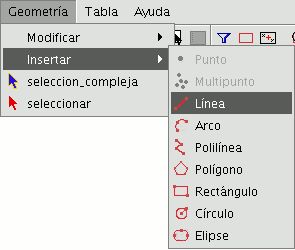
or go to the “Geometry” menu bar then to “Insert” and “Line”.
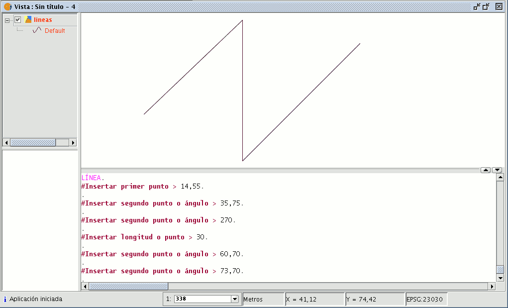
Place the cursor inside the graphic area and insert the line vertices in the desired points. gvSIG will create a projection from the last inserted point to the mouse pointer which you can use as a reference point to set the points in the drawing. You can also draw a line from the command console. Write the command “line” and then input the coordinates to define the points which delimit the segments which make up the line.
You can also insert the second and/or successive points by defining a distance and an angle. For example, to insert a point 1 unit away from the previous point at a 45º angle, write 1<45. The following image shows how a third point is inserted, after inserting the first and second points, one unit away from the previous point at a 180º angle.
Arco
You can draw an arc by clicking on the “Arc” button in the tool bar

or by going to the “Geometry” menu bar then to “Insert” and “Arc”.
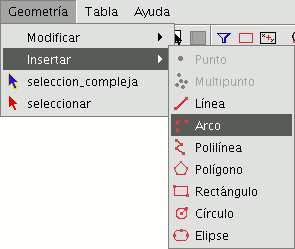
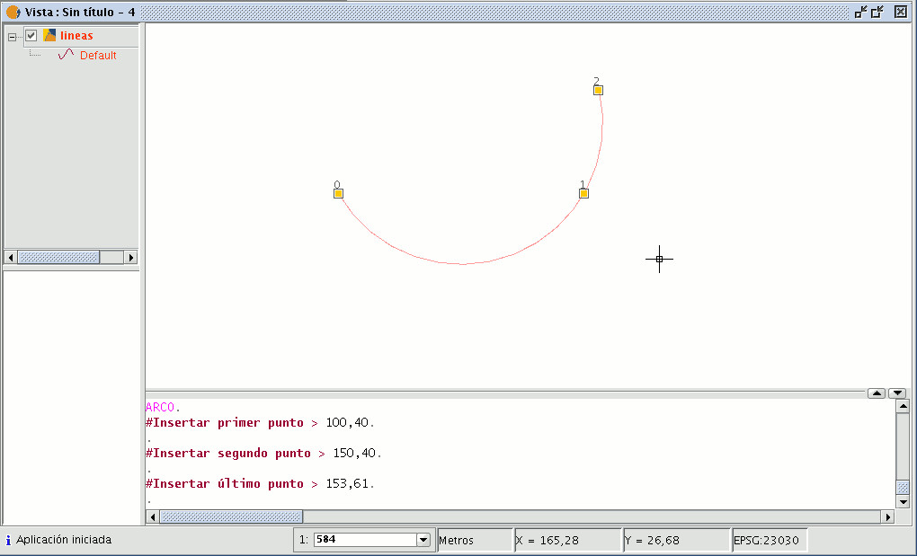
Three points are requested to draw an arc. The first and last points mark the initial and final points of the arc and the second one marks an intermediate point through which the hypothetic circle of which the arc is a part would pass. To insert an arc from the command console, write the command “arc”. The three points required to define the arc will be requested one after another.
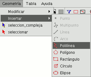
Polilínea
This feature can be a set of arcs and/or segments combined by the user. You can draw a polyline by selecting the tool from the edition tool bar and clicking on the “Polyline” button

or by going to the “Geometry” menu bar then to “Insert” and “Polyline”.
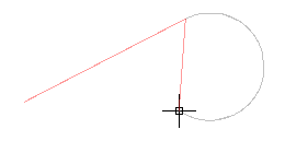
The polyline allows you to insert straight lines in the graphic area, but these differ from standard lines in that they allow you to insert an arc from the last vertex, to which it will always be located at a tangent, and end the polyline thus creating a polygon. Click on the graphic area in the place you wish the first point of the polyline to be located and insert the following points by left clicking on the mouse in the places you wish to locate them. If you wish to draw an arc, right click on the mouse and select the “Internal arc” option in the contextual menu.
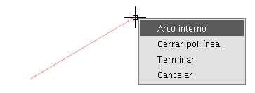
When this option has been selected, gvSIG shows a projection of an arc from the last inserted vertex to the mouse pointer.
If you wish to insert more lines, go back to the contextual menu and select the “Internal line” option.
If you wish to close the figure so that a straight line is drawn from the last inserted point to the first point, select the “Close polyline” option.
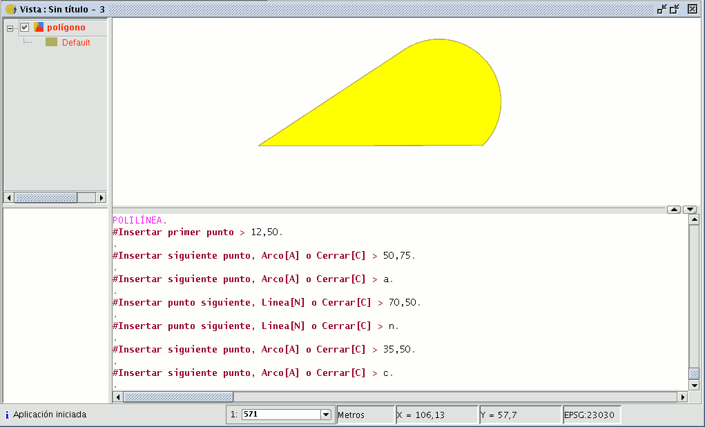
To draw a polyline from the command console, write the command “polyline”. Input the coordinates of the source point. Then you can insert the second point or input one of the parameters to draw an arc “A”, or close the polyline “C”. When you have selected the arc option, you can draw more straight lines using the parameter “N”. The following image shows how the polyline draws a straight line from the arc's last vertex to the source, thus creating a closed figure after inputting the parameter “C”.
Polígono
This option allows you to draw regular polygons which will be handled as a closed polyline. As usual, there are three ways of activating the polygon command. You can select this tool by going to the tool bar and clicking on the "Polygon" button.

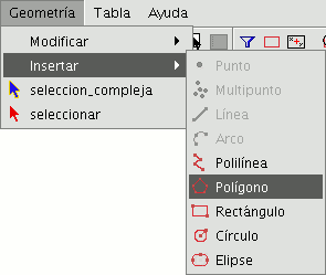
The second option way of activating the tool is by going to the “Geometry” menu bar then to “Insert” and “Polygon”.
To graphically insert a polygon in the drawing, select the tool and then click inside the graphic area on the place you which to position the polygon’s central point.
The application will generate a projection of the object. Move the mouse using the polygon projection as a reference point until it is the size you require, and click on the graphic area once again.
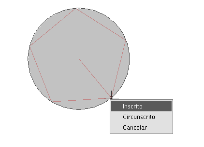
You can tell gvSIG if you wish the polygon you are drawing to be defined as inscribed or circumscribed in the circle. By default, the polygon will be inscribed in the circle. To modify this setting, define the central point of the polygon, right click on the mouse to open the contextual menu and select the desired option.
gvSIG also allows you to modify the number of sides you wish the polygon you are editing to have. To do so, select the polygon object and input the number of sides in the command console.
The third way to select this tool is from the command console. To draw a polygon from the command console, write the command “polygon”, specify the number of sides you wish the polygon to have, whether it should be drawn as inscribed or circumscribed (“I” or “C” respectively), and finally insert the radius, which must be delimited by indicating its length in the units in which the view is defined.
Rectángulo
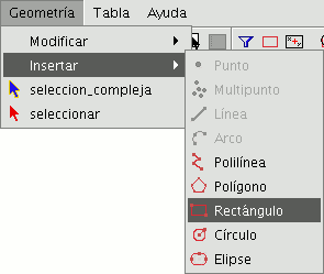
This allows you to draw a rectangle by indicating its diagonally opposite vertices. Click on the “Rectangle” button in the tool bar.

You can also select the tool by going to the “Geometry” menu bar then to “Insert” and “Rectangle”.
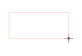
To graphically draw a rectangle in the layer you are editing, select the tool and place the first vertex in the required position in the graphic area. The application will show a projection of the rectangle you are drawing. Move the mouse, choose the position for the vertex diagonally opposite the one you have already inserted and left click on the mouse to define it.
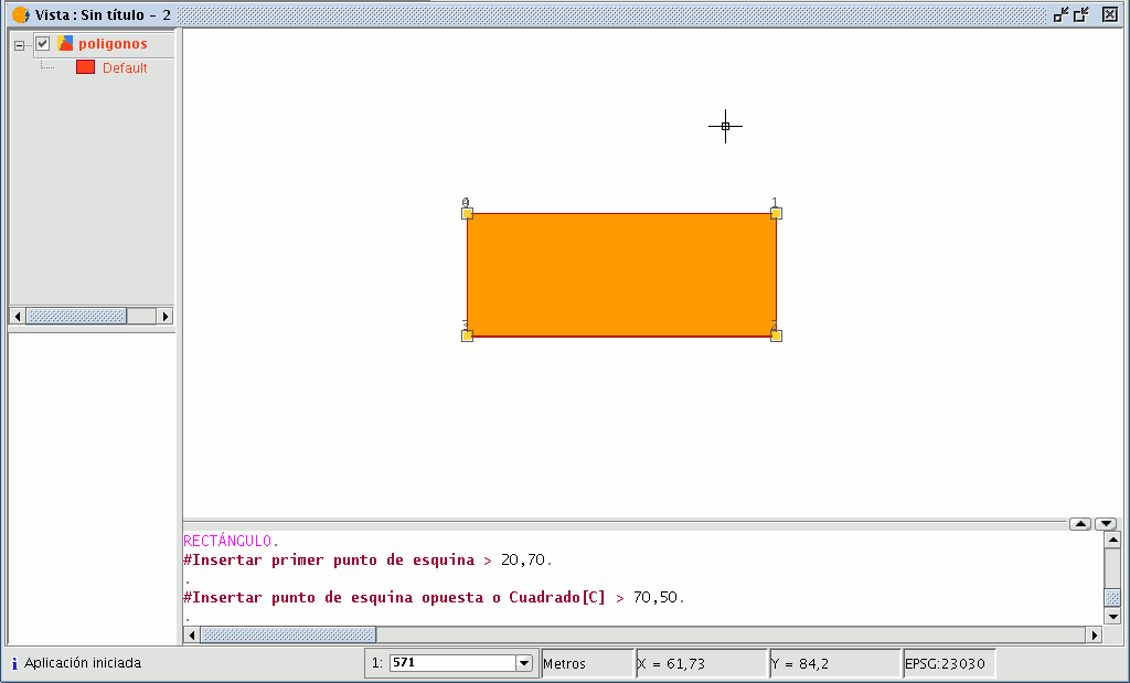
To work with the command console write the command “rectangle” and then input the coordinates for the first vertex and the diagonally opposite vertex.
Cuadrado
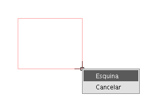
A square is simply a rectangle with equal sides. To prevent possible mistakes when drawing the square, the application allows you to create a square based on a rectangle and makes it have equal sides. To draw a square, first select “Rectangle” and insert the first vertex, then right click on the mouse and click on the “Square” option (“Corner”) in the contextual menu.
The following figure shows an example of the creation of a square from the command console. After the first point of the rectangle has been input, gvSIG is told to make the figure become a square by inputting the letter “C”. You can then insert the opposite corner.
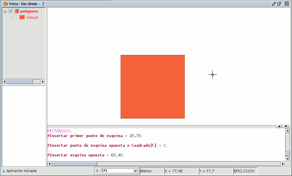
If you make a mistake in inputting the coordinates the application will still draw a square by calculating the size of the vertical line (Y axis), using the coordinate specified for the X axis.
Círculo
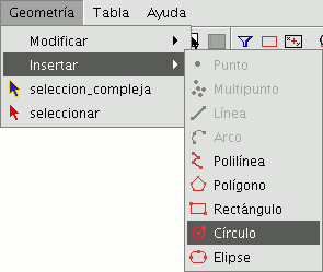
This command draws a circle inside the graphic area. You can select this tool by clicking on the “Circle” button in the tool bar

or by going to the “Geometry” menu bar then to “Insert” and “Circle”, as shown in the figure below.
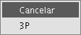
There are two ways of defining a circle. The first option is to define the central point and the radius. Select the “Circle” tool and click on the graphic area in the place you wish to locate the centre of the circle you are drawing. Then move the mouse to increase the radius of the circle until it reaches the required size. gvSIG will, as always, create a projection of the circle as a reference point to show the position of the circle in the drawing. The second way of drawing a circle in gvSIG is to define it by using three points. To access this option to define a circle, first select the tool and then go to the contextual menu by right clicking on the mouse in the graphic area.
There is only one circle that goes through three given points. When you use this option an elastic circle appears. It is defined by these two points and the cursor until we define the third point, as shown in the figure below.
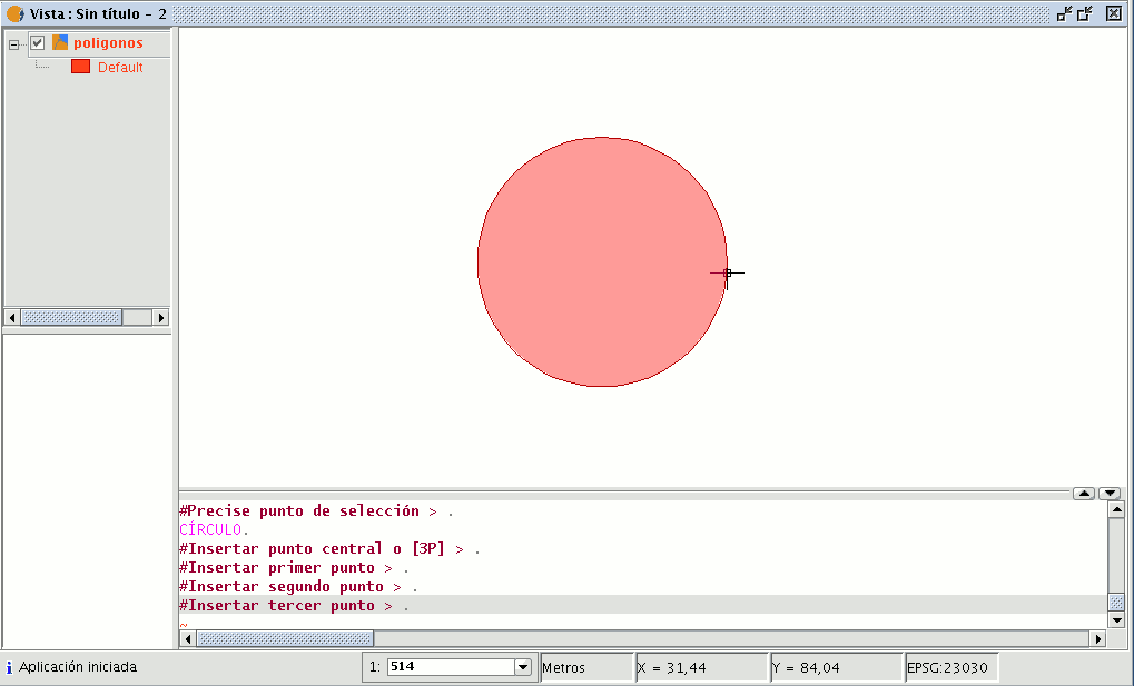
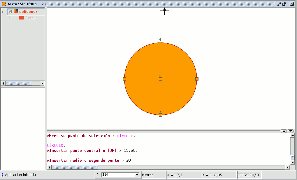
You can also draw a circle from the command console using any of the methods described above for graphic drawing. Write the command “circle” in the command console and press “Enter”. Insert the coordinates of the central point and then the coordinates of the point that will mark the desired radius or length (use the status bar to check whether you are working in metres or another measuring unit).
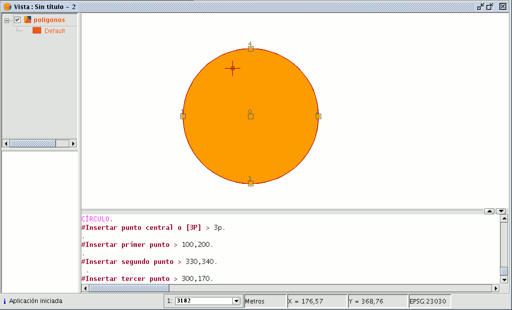
To insert a circle from the command console by defining three points, write “3p” when the “circle” command has been activated. When you use this option an elastic circle appears. It is defined by these two points and the cursor until we define the third point, as with the case of the graphic drawing of the circle. The figure below shows how to create a three-point circle.
Elipse
An ellipse is defined by an axis and the length of the second axis to the centre of the ellipse. There are, as always, three ways of selecting the ellipse drawing tool. To graphically draw an ellipse you can click on the “Ellipse” button in the edition tool bar.

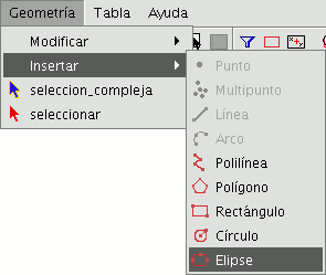
The second option is by going to the “Geometry” menu bar then to “Insert” and “Ellipse”.
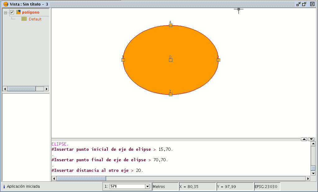
To graphically draw an ellipse, indicate the initial and final points of the ellipse’s axis by left clicking on the mouse in the corresponding places. When the initial point has been input an elastic line will be shown which can be used as a reference point to mark the final point of the axis. When it has been set the ellipse projection will be shown until the third point which marks the distance to the other axis is defined.
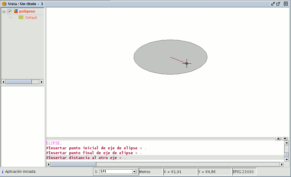
To draw an ellipse from the command console, write the command "ellipse". When gvSIG requests the initial point of the ellipse axis, indicate the point coordinates. It will then request the final point of the axis and finally the distance to the other axis.
Edición alfanumérica (Tablas)
Introducción
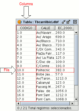
A table is part of a data base. It is made up of rows or records and columns or fields which contain the alphanumeric information needed to characterise the elements (polygons, lines or points) which make up the theme maps, cartography in general and graphs. The rows represent elements or objects and the columns represent the variables or attributes associated with each element.
In general terms, there are two types of tables; “internal” tables which are typical of an information layer and are found in the same file and “external” tables which can be added to a gvSIG project. Each element (point, line or polygon) of a layer only has one record in that layer’s table of attributes.
Pasos a seguir en una sesión de edición de una tabla 'interna'.
Open a “View” and add the layer you wish to work with.
Remember that to start an alphanumeric editing process in gvSIG, you must put the layer you are working with in editing mode. In order to do this, select the layer in the ToC, go to the “Layer” menu and select “Start edition”. Select the “See table of attributes” button

or go to the “Layer” menu and select “See table of attributes”.
The table associated with the layer will be automatically added to the project.
If you go to the “Project Manager” and select the “Tables” type of document, you can check that the table shown in the view is included as a separate document in the project.
To finish the table editing session, go to the “Layer” menu and select “Finish edition”. When the session finishes a message appears asking if you would like to save the changes. Click on “Yes” to save all the changes made in the table.
Pasos a seguir en una sesión de edición de una tabla 'externa'.
- Go to the gvSIG’s “Project Manager”, and select the “Tables” type of document.
- Click on “New”.
- Click on “Add” and open the table you wish to edit.
- When you click on “Open” the table is displayed automatically on the screen.
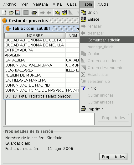
- Go to the “Table” menu and select “Start edition”.
Edición de la tabla de atributos de una capa
Añadir un registro
To add a new record to a table associated with a layer, a graphic element must be inserted. When an element is added to the associated table a new blank record appears.
Enter the data for the new entity and press “Enter”.
N.B.: Remember that if you wish to delete the selection, you can go to the tool bar and click on “Clear selection” or you can use the menu bar by clicking on the “Layer” menu and then on “Clear selection”.

N.B.: You can create a new layer with the elements selected in the table if you wish. To do so, close the table, go to the menu bar and click on the “Layer” option and then on “Export to ...”. Then select the format you wish to create the new layer with.
Modificar un registro
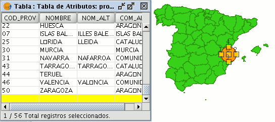
To modify the data of a layer element saved in the table, select the element whose data you wish to modify. The record that corresponds to the selected graphic element is highlighted in yellow in the table of attributes.
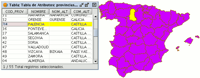
Left click on the cell in which the record to be modified is located. The record changes and a cursor appears to indicate that the data can be input.

Eliminar un registro
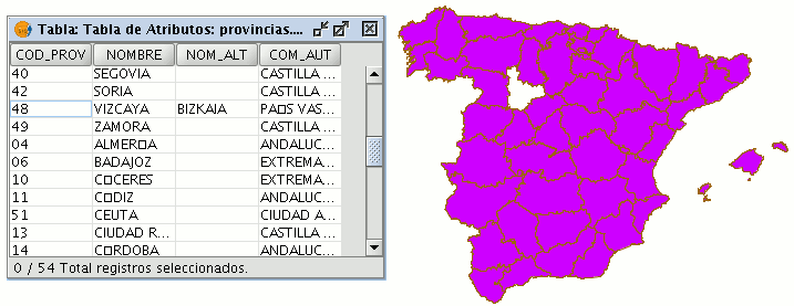
To remove a record from the table, you must first select the record.

Go to the “Table” menu and select “Remove row”.
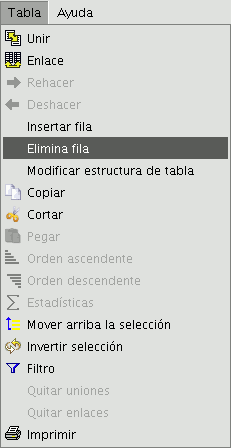
The selected record is deleted from the table and the associated graphic element disappears from the view.
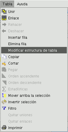
Modificar la estructura de una tabla
This tool allows you to add, delete or rename fields. To access this tool, go to the “Table” menu and select “Manage fields”.
(An error occurs when you try to change the structure of a table hosted in a postgresql data base above version 7.4. To modify the structure, use a suitable data base manager).
When the menu option is selected, a window appears in which the fields of the selected table and the buttons to create a new field or delete or rename an existing field are included.
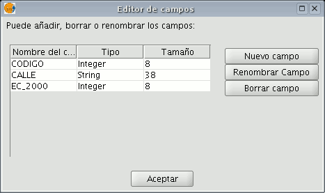
If you click on “New field”, a new window appears in which some of the properties of the new field to be added to the table can be configured.
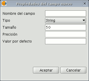
Field name: Enter the name of the new field. Type: If you click on the arrow on the right, a pull-down menu appears in which the type of field data (string, double...) can be configured.
Length: Indicate the required length of the field. Debe tener en cuenta que el tamaño máximo para un campo de tipo string es 254.
Precision: Indicates the number of decimals a numerical field must have (only for numerical type fields).
Default value: Indicates the default value for the field when no specific value is defined in the table.
If you wish to use the delete tool (“Delete field”) and the renaming tool (“Rename field”), simply select the field to be modified and click on the corresponding button.
-----------------------------------
- Error 'You are not allowed to access 'getId' in this context' accediendo al documento Introducción, [Manual de usuario, Herramientas de edici\xf3n, Introducci\xf3n]
